検証日時
02/01/2015 (Sun)
概要
Gazeboのチュートリアル第二弾「Build a Robot」。
レベル
BEGINNER
環境
PC
:
Lenovo ThinkPad X240
Prosessor
:
Intel Core i7-4600U (2.10GHz, 4MB, 1600MHz)
RAM
:
PC3-12800 DDR3L (8GB)
OS
:
Ubuntu 14.04 LTS 64bit
Kernel
:
3.13.0-44-generic
Gazebo
:
Version 5.0.1
参考
GAZEBO Tutorial-Build a Robot
はじめに
始める前に以下を参照してください(してない人は)
このチュートリアルでは、すでに存在するロボットの部品を組み立てて、新しいロボットを作るにはどうするかについて説明します。例えば、移動ロボットに簡単な腕とグリッパを取り付けると言った具合です。
ロボットの組み立て
Gazeboを立ち上げてください。その際に、以前のチュートリアルで製作したロボットを読み込むことができるか確認してください。
移動台車ベース
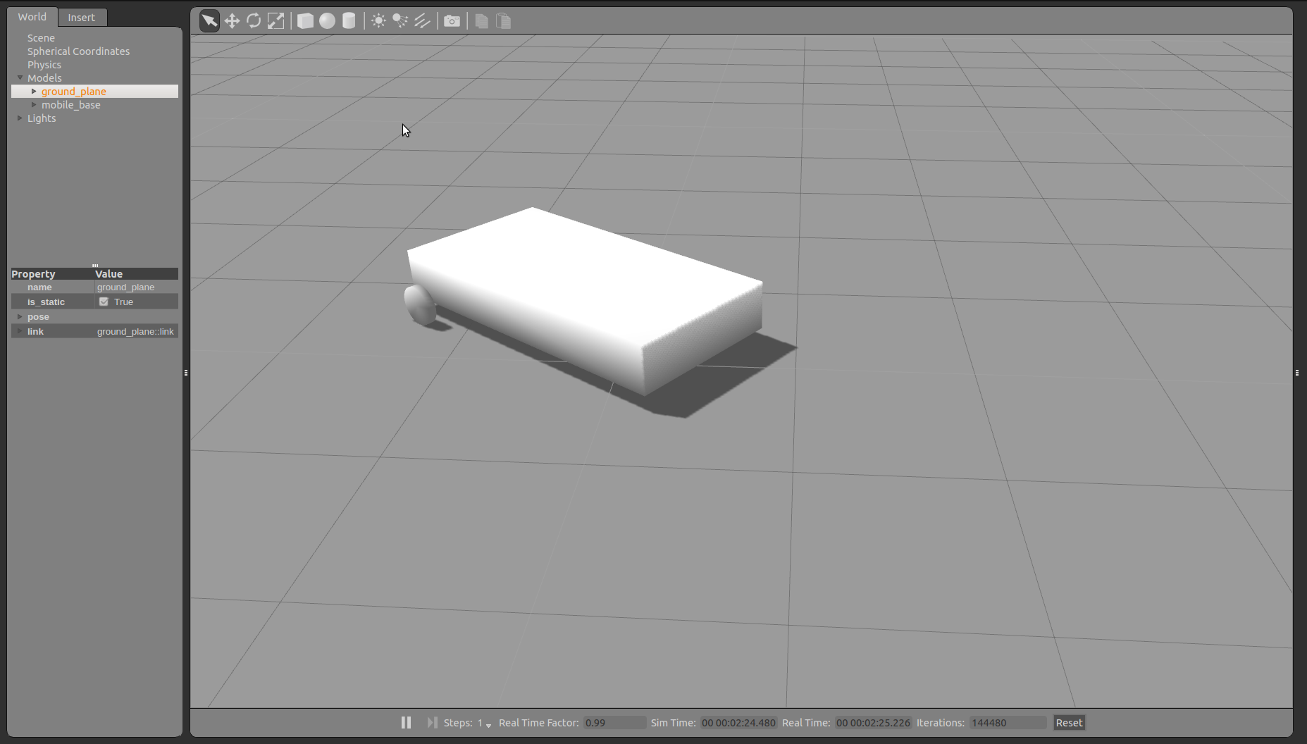
以前移動ロボットを作る で以下のような移動ロボット(台車)を作成したはずです。
このチュートリアルでは~/.gazebo/models/my_robot/model.sdfを修正し、モデルをより大きくすることでグリッパを搭載します。故に、以下のようにして、model.sdfを修正してゆきましょう。:
1
gedit ~/.gazebo/models/my_robot/model.sdf
以下のようにして、モデルを大きくし、タイヤの位置を設定し直します。
1
2
3
4
5
6
7
8
9
10
11
12
13
14
15
16
17
18
19
20
21
22
23
24
25
26
27
28
29
30
31
32
33
34
35
36
37
38
39
40
41
42
43
44
45
46
47
48
49
50
51
52
53
54
55
56
57
58
59
60
61
62
63
64
65
66
67
68
69
70
71
72
73
74
75
76
77
78
79
80
81
82
83
84
85
86
87
88
89
90
91
92
93
94
95
96
97
98
99
100
101
102
103
104
105
106
107
108
109
<?xml version='1.0'?>
<sdf version= '1.4' >
<model name= "mobile_base" >
<link name= 'chassis' >
<pose> 0 0 .25 0 0 0</pose>
<inertial>
<mass> 20.0</mass>
<pose> -0.1 0 -0.1 0 0 0</pose>
<inertia>
<ixx> 0.5</ixx>
<iyy> 1.0</iyy>
<izz> 0.1</izz>
</inertia>
</inertial>
<collision name= 'collision' >
<geometry>
<box>
<size> 2 1 0.3</size>
</box>
</geometry>
</collision>
<visual name= 'visual' >
<geometry>
<box>
<size> 2 1 0.3</size>
</box>
</geometry>
</visual>
<collision name= 'caster_collision' >
<pose> -0.8 0 -0.125 0 0 0</pose>
<geometry>
<sphere>
<radius> .125</radius>
</sphere>
</geometry>
<surface>
<friction>
<ode>
<mu> 0</mu>
<mu2> 0</mu2>
</ode>
</friction>
</surface>
</collision>
<visual name= 'caster_visual' >
<pose> -0.8 0 -0.125 0 0 0</pose>
<geometry>
<sphere>
<radius> .125</radius>
</sphere>
</geometry>
</visual>
</link>
<link name= "left_wheel" >
<pose> 0.8 0.6 0.125 0 1.5707 1.5707</pose>
<collision name= "collision" >
<geometry>
<cylinder>
<radius> .125</radius>
<length> .05</length>
</cylinder>
</geometry>
</collision>
<visual name= "visual" >
<geometry>
<cylinder>
<radius> .125</radius>
<length> .05</length>
</cylinder>
</geometry>
</visual>
</link>
<link name= "right_wheel" >
<pose> 0.8 -0.6 0.125 0 1.5707 1.5707</pose>
<collision name= "collision" >
<geometry>
<cylinder>
<radius> .125</radius>
<length> .05</length>
</cylinder>
</geometry>
</collision>
<visual name= "visual" >
<geometry>
<cylinder>
<radius> .125</radius>
<length> .05</length>
</cylinder>
</geometry>
</visual>
</link>
<joint type= "revolute" name= "left_wheel_hinge" >
<pose> 0 0 -0.03 0 0 0</pose>
<child> left_wheel</child>
<parent> chassis</parent>
<axis>
<xyz> 0 1 0</xyz>
</axis>
</joint>
<joint type= "revolute" name= "right_wheel_hinge" >
<pose> 0 0 0.03 0 0 0</pose>
<child> right_wheel</child>
<parent> chassis</parent>
<axis>
<xyz> 0 1 0</xyz>
</axis>
</joint>
</model>
</sdf>
すると以下の様になっているはずです。
ロボットを組み立てる
簡単なグリッパを取り付けたロボットを作成するために、新しいモデルディレクトリを作成しましょう。
1
mkdir ~/.gazebo/models/simple_mobile_manipulator
そしてモデルのConfigファイルmodel.configを編集しましょう。
1
gedit ~/.gazebo/models/simple_mobile_manipulator/model.config
作成するmodel.configの内容は以下のようにしましょう。
1
2
3
4
5
6
7
8
9
10
11
12
13
<?xml version="1.0"?>
<model>
<name> Simple Mobile Manipulator</name>
<version> 1.0</version>
<sdf version= '1.4' > manipulator.sdf</sdf>
<author>
<name> My Name</name>
<email> me@my.email</email>
</author>
<description>
My simple mobile manipulator
</description>
</model>
続いて、モデルのSDFファイルmanipulator.sdfを作成しましょう。:
1
gedit ~/.gazebo/models/simple_mobile_manipulator/manipulator.sdf
作成するmanipulator.sdfの内容は以下のようにしましょう。
1
2
3
4
5
6
7
8
9
10
11
12
13
14
15
16
17
18
19
20
21
22
23
24
25
26
27
28
29
30
31
32
33
34
35
36
37
38
39
40
<?xml version="1.0" ?>
<sdf version= "1.3" >
<model name= "simple_mobile_manipulator" >
<include>
<uri> model://my_gripper</uri>
<pose> 1.3 0 0.1 0 0 0</pose>
</include>
<include>
<uri> model://my_robot</uri>
<pose> 0 0 0 0 0 0</pose>
</include>
<joint name= "arm_gripper_joint" type= "revolute" >
<parent> mobile_base::chassis</parent>
<child> simple_gripper::riser</child>
<axis>
<limit>
<lower> 0</lower>
<upper> 0</upper>
</limit>
<xyz> 0 0 1</xyz>
</axis>
</joint>
<!-- attach sensor to the gripper -->
<include>
<uri> model://hokuyo</uri>
<pose> 1.3 0 0.3 0 0 0</pose>
</include>
<joint name= "hokuyo_joint" type= "revolute" >
<child> hokuyo::link</child>
<parent> simple_gripper::palm</parent>
<axis>
<xyz> 0 0 1</xyz>
<limit>
<upper> 0</upper>
<lower> 0</lower>
</limit>
</axis>
</joint>
</model>
</sdf>
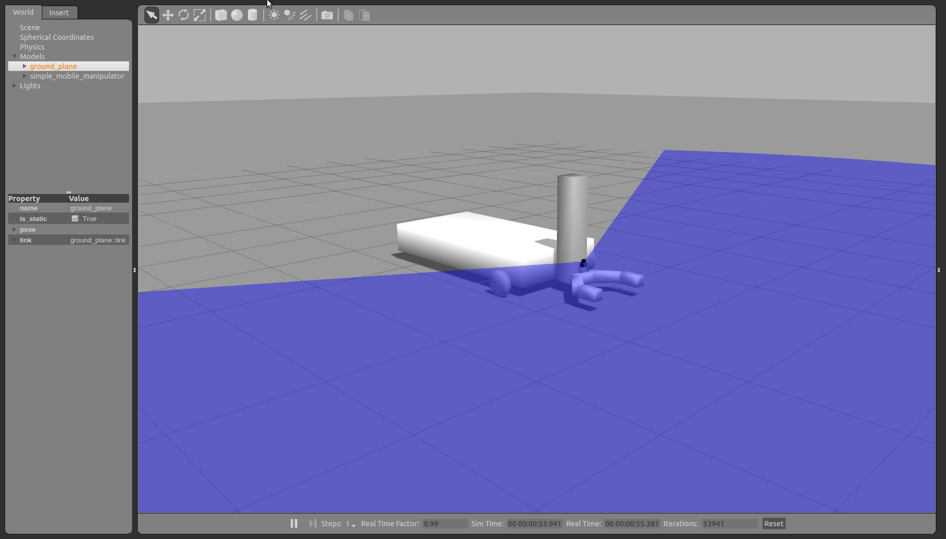
編集したmodel.configとmanipulator.sdfをセーブしたら、Gazeboを立ち上げ、Insert タブよりSimple Mobile Manipulator モデルを選択して、作成したモデルをシミュレータに表示してください。すると、以下のようになっているはずです。